Fitting an ATI Radeon 4870 in a Silverstone SG05 miniITX chassis.

I recently got hold of a Silverstone SG05 mini ITX chassis to build a small and portable gaming PC. The aim was to build a small, yet powerful machine that would be easy to haul around.

Anyway, the specifcations consist of the following:

Zotac GeForce 9300-ITX WiFi (miniITX motherboard)
Intel E5400 (2.7GHz) Pentium Dual core CPU. (Overclocked to 3.2 GHz)
2GB OCZ DDR800 RAM
Silverstone SG05 miniITX chassis with 300w PSU
Seagate 500GB 7200rpm Hard disk.

To start I left the machine running with just its onboard discrete graphics card (Geforce 9300). The motherboard has a full 16x PCI Express slot, but I am still deciding which graphics card will be best. (I am leaning towards an ATI 5770 for it’s low power consumption, good size and decent speed). However I saw quite a few people asking around as to what kind of cards will actually fit into the SG05 chassis and whether or not they would be able to run on the 300w PSU.

I have this Sapphire ATI 4870 512MB graphics card running in my main gaming PC. It is running a custom bios that I flashed to it a while ago, upping the default GPU core speed from 725MHz to 795MHz and the default memory speed of 900MHz to 1100MHz (4400MHz effective). It therefore uses slightly more juice than a stock 4870. I wanted to see if this card would fit or not and how it would handle running on the 300w PSU of the SG05. Well the answer is yes, it fits! Barely. It took quite a bit of manouvering to get it in there and a fair bit of time to wiggle the auxillary power connectors into the 6 pin power sockets on the end of the PCB. Here are some photos for those interested:

The motherboard to start:

The card resting on the chassis to size it up.

Finally in!

Here is a short video of the card running 3D Mark 2005.

httpv://www.youtube.com/watch?v=OgrUHZlbrAo

How to: Swapping out LCD panel in Acer Laptops

Here is a quick photo guide I did on how I swapped out LCD panels (between two Acer Travelmate laptops – 15″ LCD from 4520 to the 4600’s chassis). The 4600 had a faulty LCD panel and the laptop worked perfectly apart from this one problem. I guess a lot of this would be relevant when dealing with most laptop LCDs. The only change being slightly different components and connectors in slightly different places. Hope this helps someone out in the future. I just ensured both panels were the same specification : i.e. both were 1024×768, XGA and were for Acer Travelmate laptops.

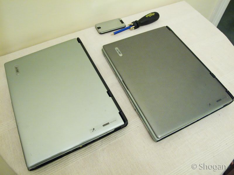
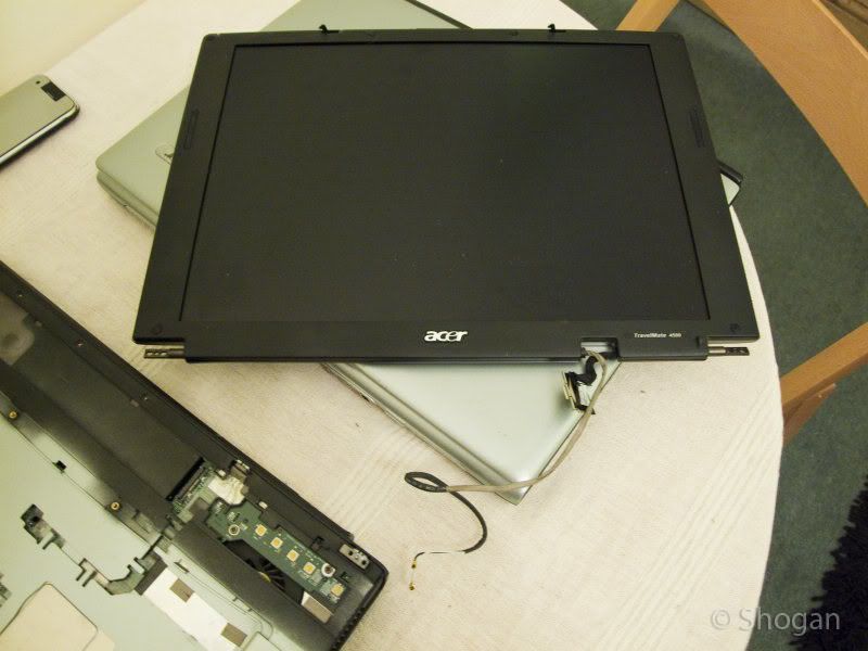
1. Here we have the two laptops. Donor laptop in dark grey, laptop to receive new LCD in light grey.

Start by removing your mains charger and disconnecting your laptop battery.

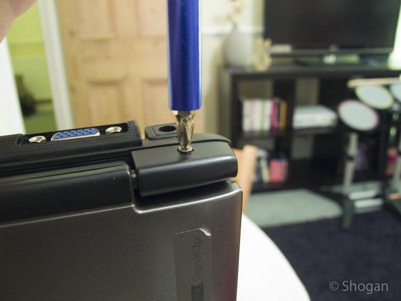
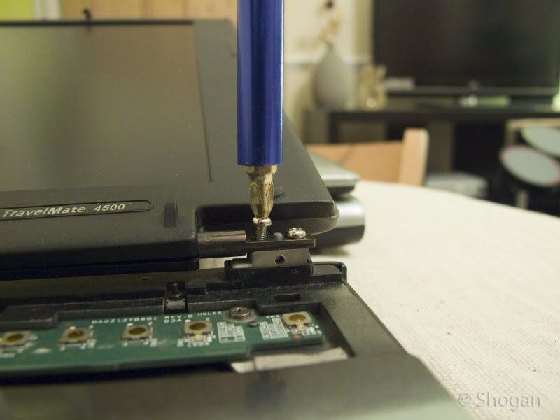
2. Flip the donor laptop on its edge, and unscrew the 3 screws on the back of the LCD hinges.

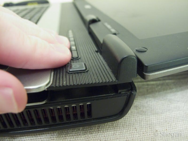
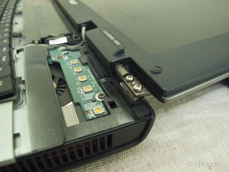
3. Next, fold the LCD backwards (open it as far as it will go), and pry off this plastic panel (gently as you can with your fingers). If you are gentle and patient enough, it should come off relatively easily without snapping anything.

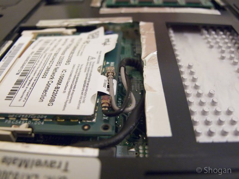
4. Flip the laptop over and unscrew the cover that protects the wifi and RAM components. On these laptops this is in the center.

You will find that there should be two “pigtail” connectors attaching to your wifi card – these are labelled AUX and MAIN. (note down which colour wire attaches to which connector) – mine was black on AUX and White on MAIN. Disconnect these two pigtail connectors as these run through the notebook, up into the LCD to give you a better wireless signal.

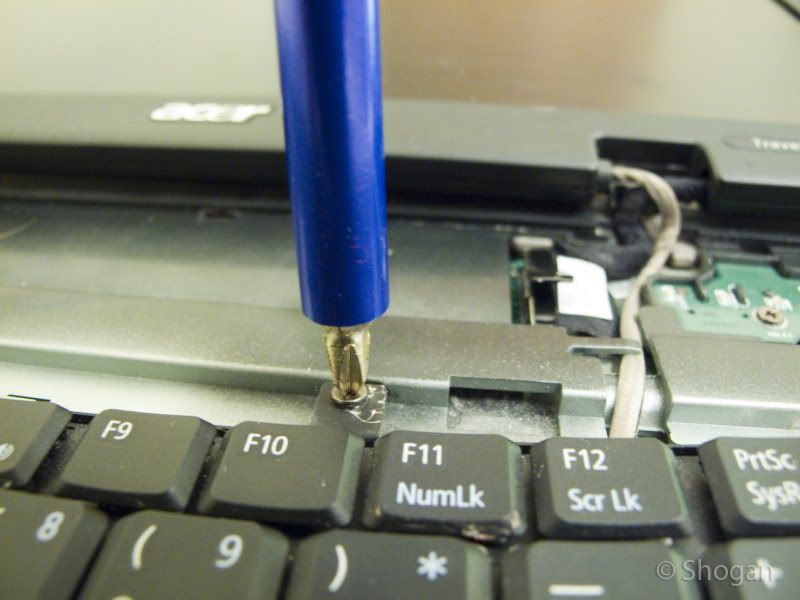
5. Next we flip the laptop over again, and unscrew these two screws to remove the keyboard.

Lift the keyboard gently and notice the ribbon connector that attaches to the motherboard. Flick the black clip on this ribbon connector upwards and the ribbon connector can now be removed.

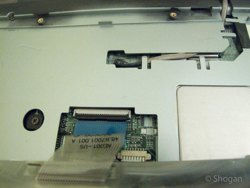
6. You can now tug carefully on the pigtail connector that runs under the keyboard and onto the wireless card (we have previously disconnected the pigtails). Pull this out until it is free from under the laptop. Be careful when it goes through the small hole on the motherboard.

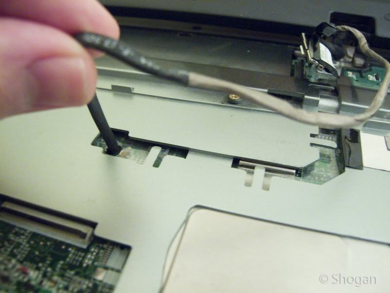
7. The main black coloured cable coming out from the LCD and connecting on to the motherboard is your main LCD connection. Carefully lift this off the motherboard, using the tag on the back of the connector to pull.

8. Once both the LCD cables are free we can now unscrew the main screws holding the LCD on to the laptop chassis. On these acers there are two on each side. PS. keep all your screws in a safe place so we can put everything back later!

9. We should now have a separate laptop LCD disconnected from the main chassis.

10. Do the same procedure as above but this time for the laptop that is going to receive the working LCD. Don’t get these muddled up now!

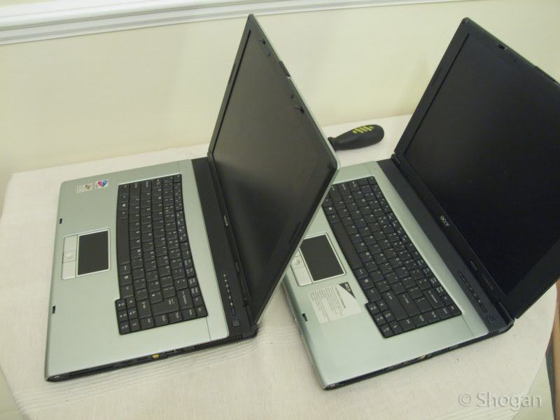
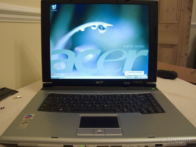
11. Once I had the working LCD off the other laptop, I hooked the main connector up to the receiving laptop with it lying down on the table to test. This was to ensure the new LCD was compatible and working as expected. See image below:

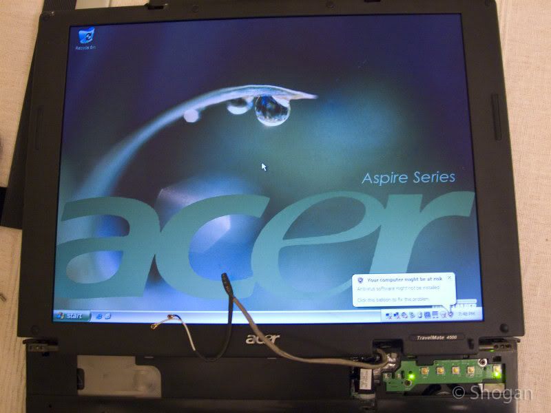
12. This was working so I shut the laptop down, removed the battery again and proceeded to remove the LCD from the top lid’s chassis to swap out. (I could have just moved the entire lid from one to the other laptop but the colour was slightly different and I was fussy)!

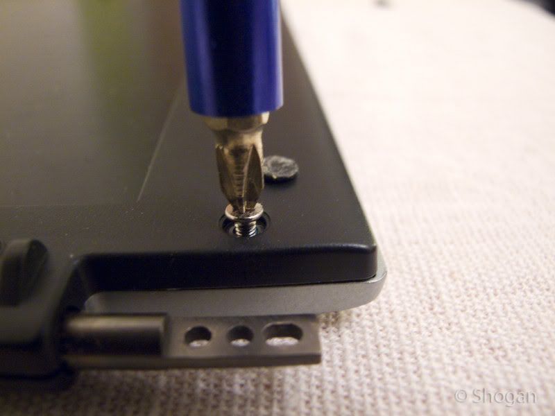
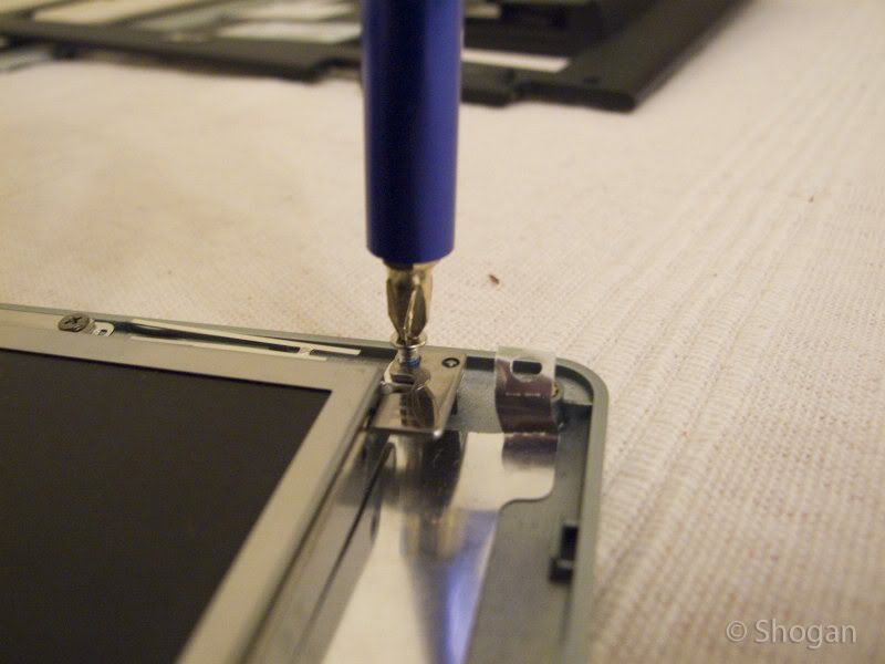
Start by removing the 4 x rubber pads from each corner of the LCD and unscrewing these 4 x screws.

Once done, you can now carefully pry open the edge of the LCD lid as below:

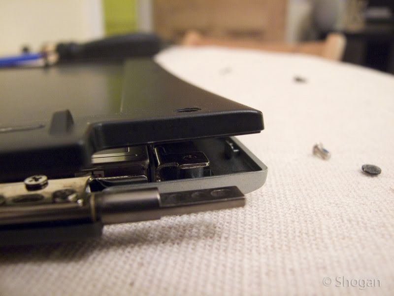
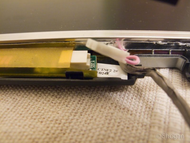
Once this has been carefully remove (The outer black frame of the lid), we can remove the screws inside the lid that hold the actual LCD panel in.

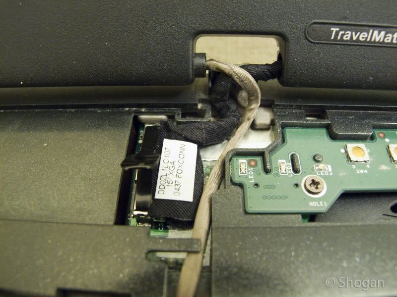
You also need to unplug the LCD controller panel’s plugs and unscrew a grounding wire.

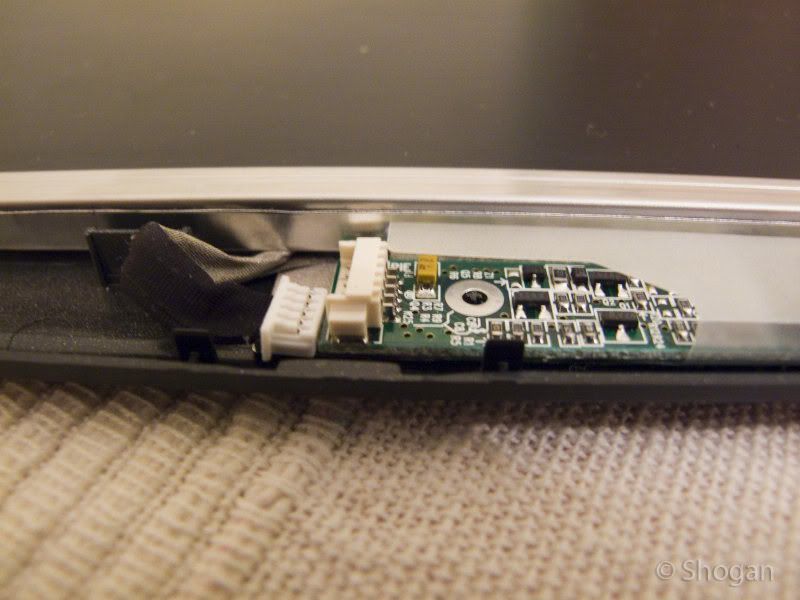
Do the same for the other LCD panel and remember which one is working and which doesn’t. Swap the working LCD over into the lid chassis you would like to use and screw everything back in. Make sure the cables are not getting pinched anywhere and run neatly out the bottom of the lid. Plug your two connectors back in to the LCD controller at the bottom of the lid and screw your grounding wire (black) back in (this is also next to the two cables at the bottom of the lid).

13. Re-assemble the lid and finally reconnect your LCD signal/power cable back to the laptop’s motherboard. Fasten the 4 x screws (2 x on each side) that hold the LCD Lid and panel to the laptop’s main chassis. Route the wireless pigtail wire back under the keyboard panel through the hole under the wireless card and reconnect the two pigtail connectors to the wireless card. Replace the back panel that covers the RAM and wireless card.

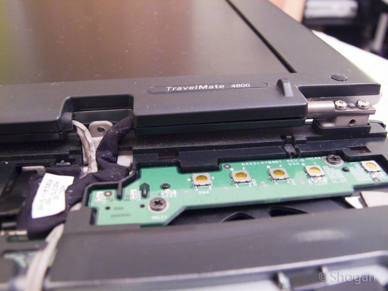
14. Place the keyboard ribbon connector back in and snap the black retainer clip over the ribbon to hold it in place. Screw the two screws back in to hold the keyboard down.

15. Replace the hinge panel over the LCD connector on the motherboard (you’ll need to fold the LCD all the back as far as it will go first). This panel is the same panel that has your power button on and is the same panel we removed earlier in step 3.

Replace the 3 x screws on the back hinges and ensure you haven’t missed any other screws anywhere and that everything looks good to go.

Replace your battery, lock the battery in and power up. You should hopefully now have a working LCD! Enjoy.

Hope this helps someone wanting to fix or replace their LCD panel in the future!

How to restart a slave FortiGate firewall in an HA cluster

Here’s a quick how-to on restarting a specific member of a High Availability FortiGate hardware firewall cluster. I have only tested this on a cluster of FG60 units, but am quite sure the steps would be similar for a cluster of FG100s, FG310s etc…

get-ha-status

First of all you may or may not want to set up some monitoring going to your various WAN connections on the HA cluster. Restarting the slave unit should not have any effect on these connections in theory as your master unit is the one handling all the work. The slave is merely there to take over should things go pear shaped on the master unit. When the slave restarts you can watch your ping statistics or other connections just to ensure everything stays up whilst it reboots.

1. Start by logging in to the web interface of your firewall cluster. https://ipaddress

2. Specify a custom port number if you have the management GUI on a custom port for example https://ipaddress:555

3. Login and look for “HA status” under the status area – this should be the default page that loads. It should show as “Active-passive” if this is the mode your HA cluster is in. Click the [Configure] link next to this.

4. This will give you an overview of your HA cluster – you can view which unit is the Master and which is the slave. This step is optional and just gives you a nice overview of how things are looking at the moment. Click “View HA statistics” near the top right if you would like to view each unit’s CPU/Memory usage and other statistics.

5. Return to the “Status” home page of your firewall GUI. Click in the “CLI Console” black window area to get to your console. (Optionally, you could also just SSH in if you have this enabled).

6. Type the following command to bring up your HA cluster details: get system ha status

7. This will show which firewall is master and slave in the cluster e.g.

Master:129 FG60-1 FWF60Bxxxxxxxx65 1
Slave :125 FG60-2 FWF60Bxxxxxxxx06 0

Look for the number right at the end and note this down. In the above example the Slave unit has the number “0” . Note this down.

8. Next enter the following command: execute ha manage x

Where “x” is the number noted down in step number 7.

This will change your management console to this particular firewall unit. i.e. the slave unit in our case. You should notice your command line change to reflect the name of the newly selected HA member.

9. Enter the following command to reboot the slave: execute reboot

10. Press “Y” to confirm and reboot the slave.

Monitor your ping / connection statistics to ensure everything looks fine. Give it a minute or so to boot up again, then return to your HA statistics page to ensure everything looks good.

That is all there is to it.

Change iPhone root SSH password

If you have jailbroken your iPhone and have SSH installed it is a very good idea to change your default root password. The default root password for the iPhone 3G is “alpine” many people know this and if you are not careful you could get someone gaining access to your phone over your service providers’ data network or over a local wifi connection.

iphone-ssh

Once SSH is installed and active login to your phone using PuTTY.  Download PuTTy here.

You will just need to specify your phone’s local wifi IP address and SSH as the connection method. When prompted, enter your username as : root and password as : alpine

Once you get a command line, type in the command “passwd” and press enter.

Enter your existing password of alpine, then specify your new root password. Be sure to keep this safe and secure! I found that after changing the root password on my phone I needed to restart it – close putty, then restart your iPhone.

Creating Primary and Secondary Domain Controllers (Windows 2003 Server)

I was creating a new Domain the other day for testing purposes and thought I would document the process as I went along to put a short tutorial up over here.

This is how to create a Primary Domain Controller (Windows Server 2003) as well as a Secondary DC to act as a backup. I will not be covering FSMO roles or changing of FSMO roles in this tutorial however. The how-to assumes that you have two freshly installed Windows 2003 Servers.

1. Create your first DC. On your first freshly installed Windows 2003 Server machine, go to Start->Run, then type “dcpromo” then hit enter. Alternatively you can go to the “Manage your server” wizard and add a new Role of “Domain Controller (Active Directory)”. After running dcpromo, click Next till you get to the “Domain Controller Type” page. Here we will select “Domain controller for new domain”.

2. Next we select “Domain in a new forest”.

3. You can now enter your full DNS name for the new domain. I used “shogan.local”. Don’t use your web domain here as this is an “internal domain name”. Use something like “yourcompanyname.local”.

4. For the netbios name, leave as default. It should just be a shortened version of your domain specified in step 3. I believe this to help with compatibility when NT, 95, 98 machines are looking at a Windows 2000 or higher domain.

5. Next you can specify the location of your database and log folders. I usually leave mine in their default location.

6. Same for the Shared System Volume folder. I leave mine as default (C:\WINDOWS\SYSVOL).

7. Next the wizard will check to see if you have DNS installed on this machine. If not, select the second option “Install and Configure the DNS server on this computer”. This is the easiest option and the installation will set DNS up for you.

8. The next screen deals with compatibility. I selected the second option here (Windows 2000 and 2003) as I won’t have any other servers below Windows 2000 or 2003 on this particular domain.

9. Enter your Directory Services restore mode password on the next screen and keep this safe.

10. Continue the wizard and the installation will begin.

11. Once the Active Directory Installation wizard is complete, click Finish, then restart the server.

12. Once it has restarted, you should get a screen stating “This Server is now a Domain Controller”. Click Finish and you are done with the first DC!

13. Next, I go to the second server with a fresh install of Windows 2003 Server.

14. Set your IP addresses up. Now that you have a DNS server on the other DC, you can point this Server’s Preferred DNS address to the IP of the Primary DC we just set up. In this case my Primary DC has an IP of 192.168.1.1 and the second DC we are about to set up gets an IP of 192.168.1.2.

15. Run dcpromo on the new server.

16. This time we are going to choose “Additional Domain Controller for an existing domain” in the Active Directory installation wizard.

17. The next screen asks you for your “network credentials”. Enter your new domain administrator username and password (Set up from the first DC). This should be “Administrator” and whatever password you specified during the install. Enter your domain name specified in step 3 above. For example I used “shogan.local”.

18. Enter the domain name again (shogan.local) in my case on the next screen.

19. Complete the rest of the installation wizard as we did in the steps for the first DC. This just involves specifying log folders etc… I usually leave the rest of the options at their defaults. Once you are done, set up should ask you to restart the server.

20. Restart once complete and login with your domain admin account. You should now have a fully functional secondary DC. Any changes you make in Active directory on either server should now replicate across to the other DC.

Here are the images related to each step of the installation process. Click any thumbnail to bring up the larger version.

Feel free to post any questions or comments in the comments section below.