AWS have a handy post up that shows you how to get CodeBuild local by running it with Docker here.
Having a local CodeBuild environment available can be extremely useful. You can very quickly test your buildspec.yml files and build pipelines without having to go as far as push changes up to a remote repository or incurring AWS charges by running pipelines in the cloud.
I found a few extra useful bits and pieces whilst running a local CodeBuild setup myself and thought I would document them here, along with a summarised list of steps to get CodeBuild running locally yourself.
Now, locate the Dockerfile for the CodeBuild image you are interested in using. I wanted to use the ubuntu standard 3.0 image. i.e. ubuntu/standard/3.0/Dockerfile.
Edit the Dockerfile to remove the ENTRYPOINT directive at the end.
# Remove this -> ENTRYPOINT ["dockerd-entrypoint.sh"]
Now run a docker build in the relevant directory.
docker build -t aws/codebuild/standard:3.0 .
The image will take a while to build and once done will of course be available to run locally.
Now grab a copy of this codebuild_build.sh script and make it executable.
Place the shell script in your local project directory (alongside your buildspec.yml file).
Now it’s as easy as running this shell script with a few parameters to get your build going locally. Just use the -i option to specify the local docker CodeBuild image you want to run.
./codebuild_build.sh -c -i aws/codebuild/standard:3.0 -a output
The following two options are the ones I found most useful:
-c – passes in AWS configuration and credentials from the local host. Super useful if your buildspec.yml needs access to your AWS resources (most likely it will).
-b – use a buildspec.yml file elsewhere. By default the script will look for buildspec.yml in the current directory. Override with this option.
-e – specify a file to use as environment variable mappings to pass in.
Testing it out
Here is a really simple buildspec.yml if you want to test this out quickly and don’t have your own handy. Save the below YAML as simple-buildspec.yml.
version: 0.2

phases:
  install:
    runtime-versions:
      java: openjdk11
    commands:
      - echo This is a test.
  pre_build:
    commands:
      - echo This is the pre_build step
  build:
    commands:
      - echo This is the build step
  post_build:
    commands:
      - bash -c "if [ /"$CODEBUILD_BUILD_SUCCEEDING/" == /"0/" ]; then exit 1; fi"
      - echo This is the post_build step
artifacts:
  files:
    - '**/*'
  base-directory: './'
Now just run:
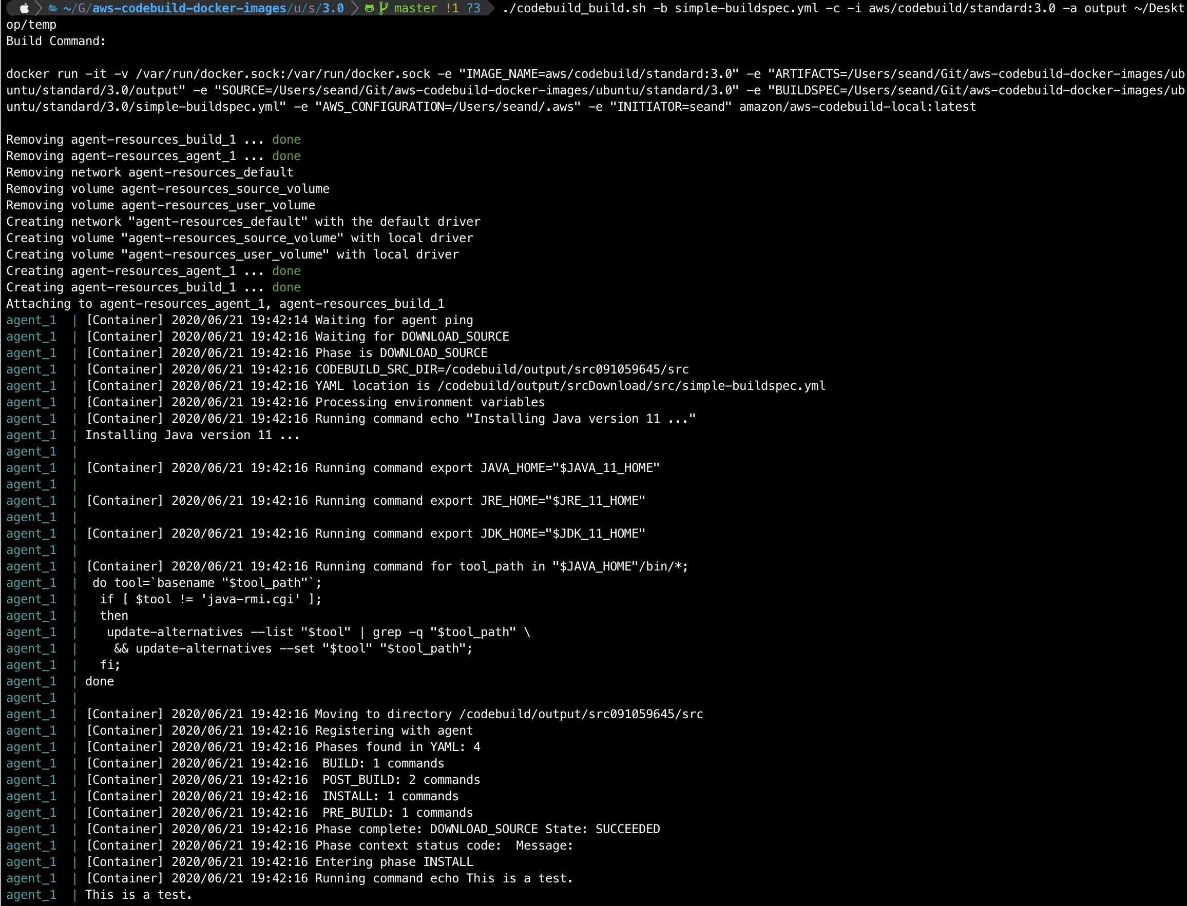
./codebuild_build.sh -b simple-buildspec.yml -c -i aws/codebuild/standard:3.0 -a output /tmp
You should see the script start up the docker container from your local image and ‘CodeBuild’ will start executing your buildspec steps. If all goes well you’ll get an exit code of 0 at the end.
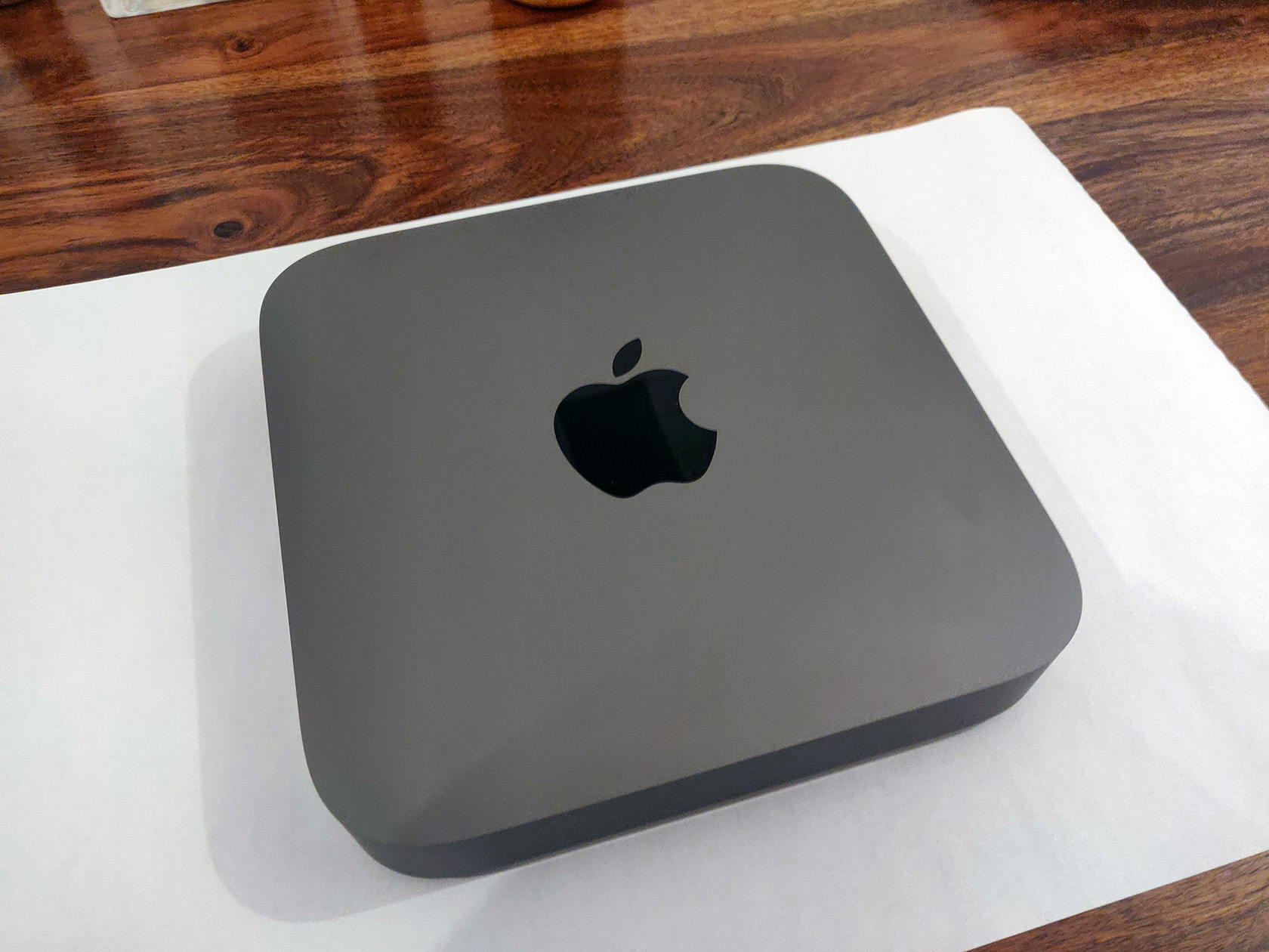
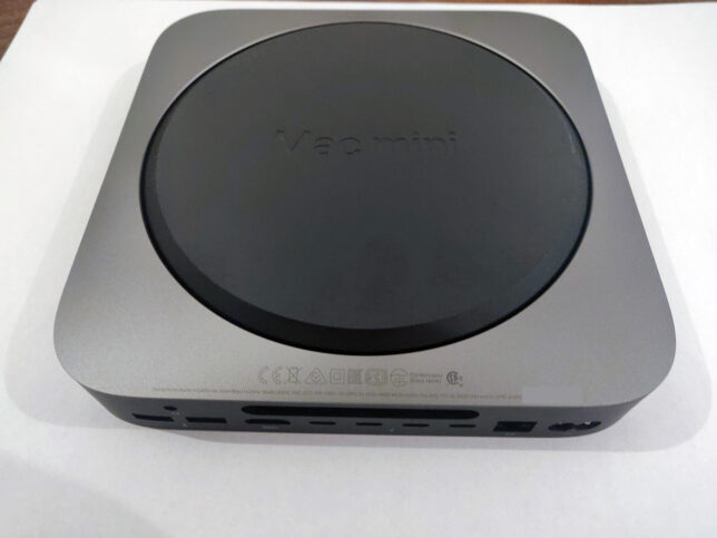
I purchased a new Apple Mac Mini recently and didn’t want to fall victim to Apple’s “RAM Tax”.
I used Apple’s site to configure a Mac Mini with a quad core processor, 32GB RAM, and a 512GB SSD.
I was shocked to see they added £600.00 to the price of a base model with 8GB RAM. They’re effectively charging all of this money for 24GB of extra RAM. This memory is nothing special, it’s pretty standard 2666MHz DDR4 SODIMM modules. The same stuff that is used in generic laptops.
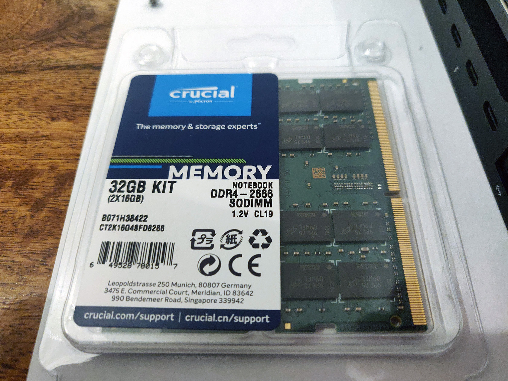
I decided to cut back my order to the base model with 8GB of RAM. I ordered a Crucial 32GB Kit (2 x 16GB DDR4-2666 SODIMM modules running at 1.2 volts with a CAS latency of 19ns). This kit cost me just over £100.00 online.
In total I saved around £500.00 for the trouble of about 30 minutes of work to open up the Mac Mini and replace the RAM modules myself.
The Teardown Process
Use the iFixit Guide
You can use my photos and brief explanations below if you would like to follow the steps I took to replace the RAM, but honestly, you’re better off following iFixit’s excellent guide here.
Follow along Here
If you want to compare or follow along in my format, then read on…
Get a good tool kit with hex screw drivers. I used iFixit’s basic kit.
Flip the Mac Mini upside down.
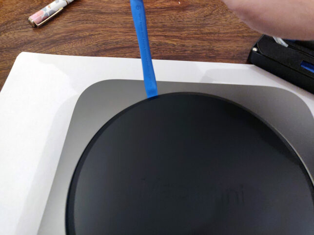
Pry open the back cover, carefully with a plastic prying tool
Undo the 6 x hex screws on the metal plate under the black plastic cover. Be careful to remember the positions of these, as there are 2 x different types. 3 x short screws, and 3 x longer.
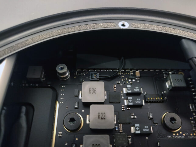
Very carefully, move the cover to the side, revealing the WiFi antenna connector. Unscrew the small hex screw holding the metal tab on the cable. Use a plastic levering tool to carefully pop the antenna connector off.
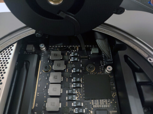
Next, unscrew 4 x screws that hold the blower fan to the exhaust port. You can see one of the screws in the photo below. Two of the screws are angled at a 45 degree orientation, so carefully undo those, and use tweezers to catch them as they come out.
Carefully lift the blower fan up, and disconnect it’s cable using a plastic pick or prying tool. The trick is to lift from underneat the back of the cable’s connector and it’ll pop off.
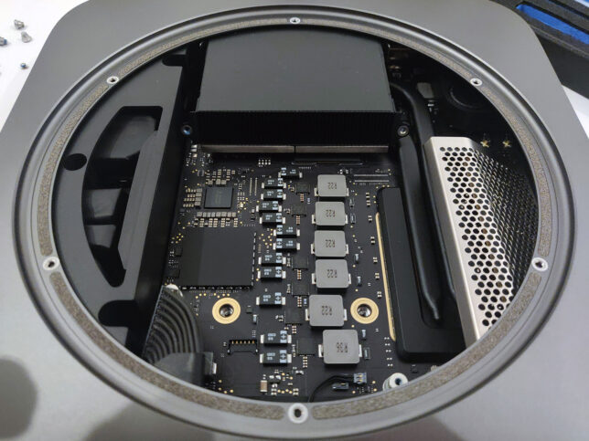
Next, disconnect the main power cable at the top right of the photo below. This requires a little bit of wiggling to loosen and lift it as evenly as possible.
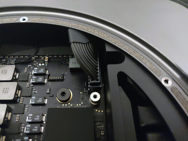
Now disconnect the LED cable (two pin). It’s very delicate, so do this as carefully as possible.
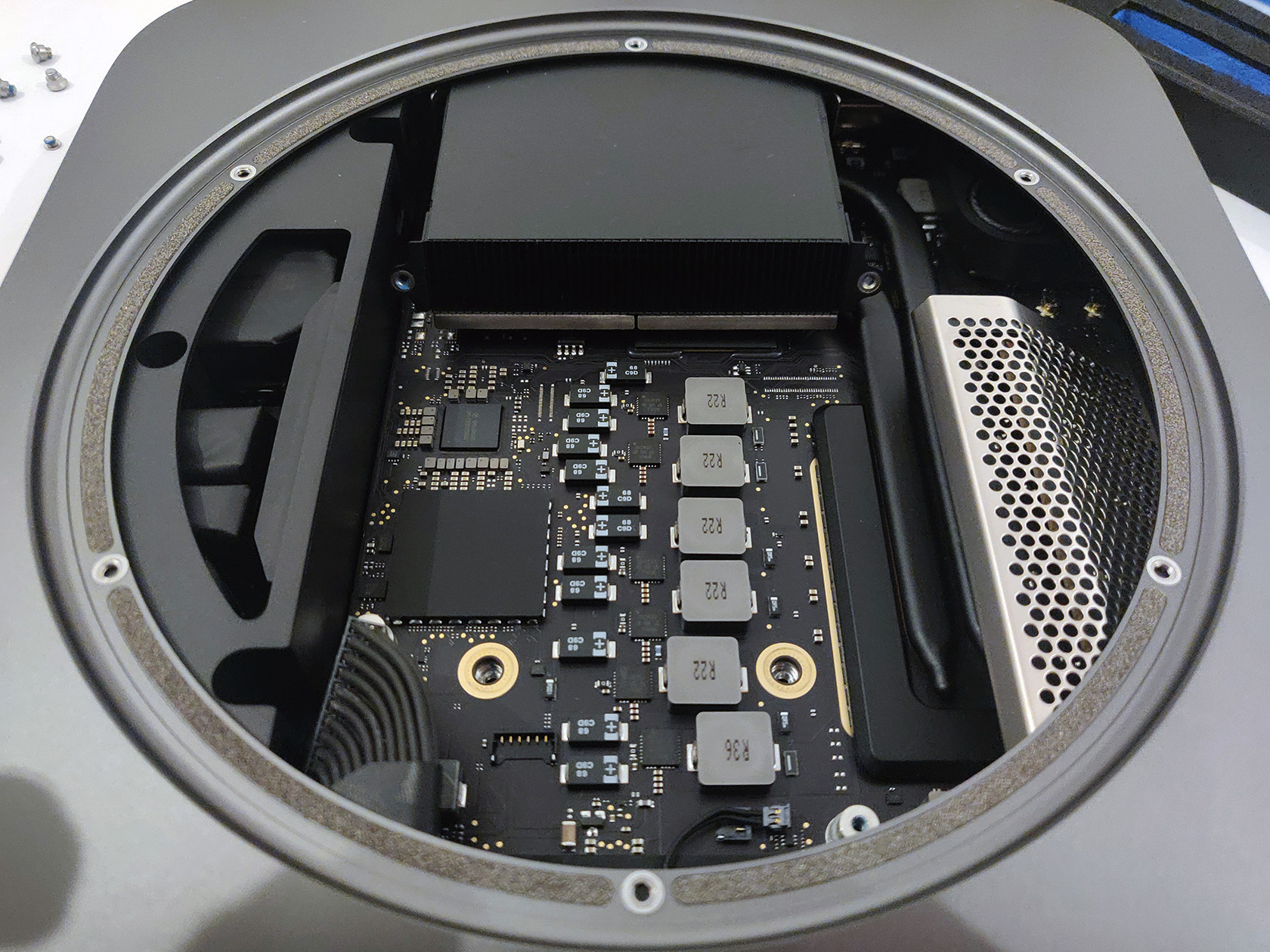
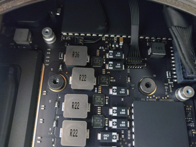
There are two main hex screws to remove from the motherboard central area now. You can see them removed below near the middle (where the brass/gold coloured rings are).
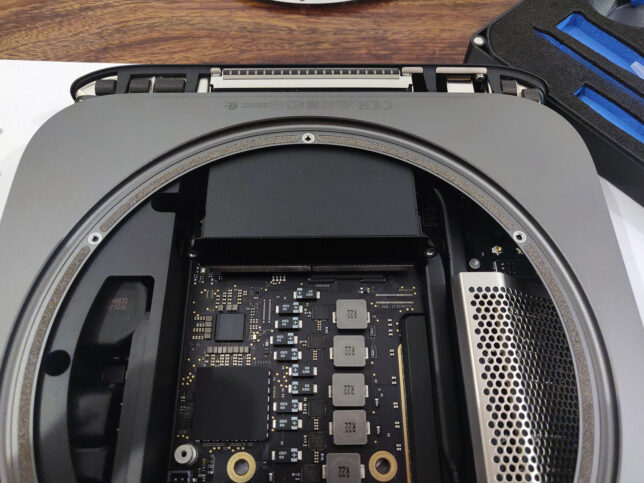
With everything disconnected, carefully push the inner motherboard and it’s tray out, using your thumbs on the fan’s exhaust port. You should ideally position your thumbs on the screw hole areas of the fan exhaust port. It’ll pop out, then just very carefully push it all the way out.
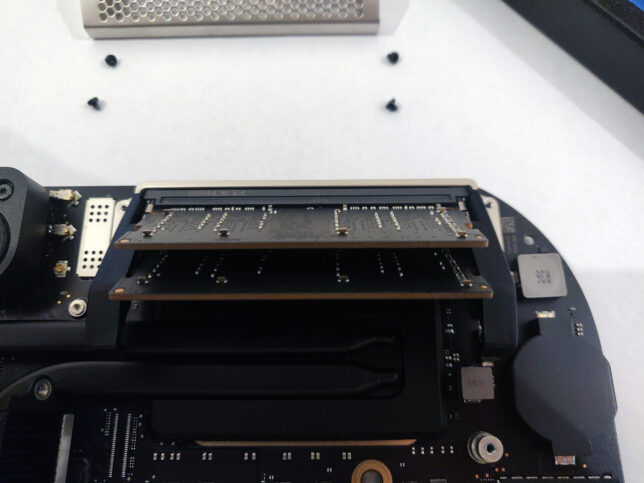
The RAM area is protected by a metal ‘cage’. Unscrew it’s 4 x hex screws and slowly lift the cage off the RAM retainer clips.
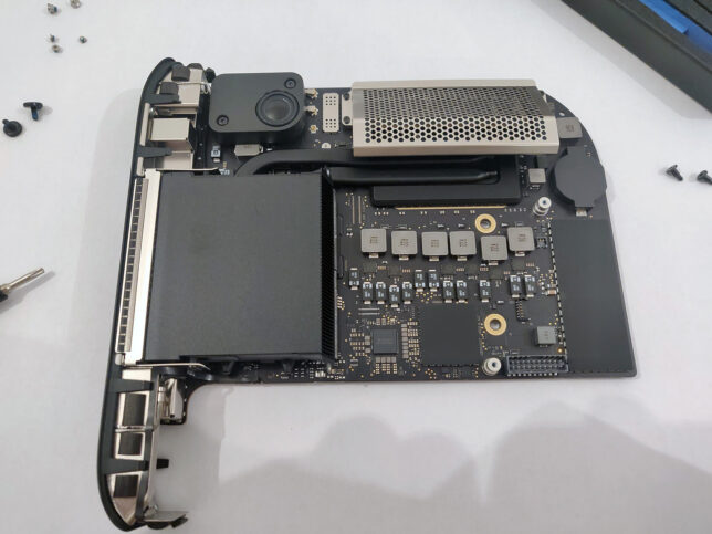
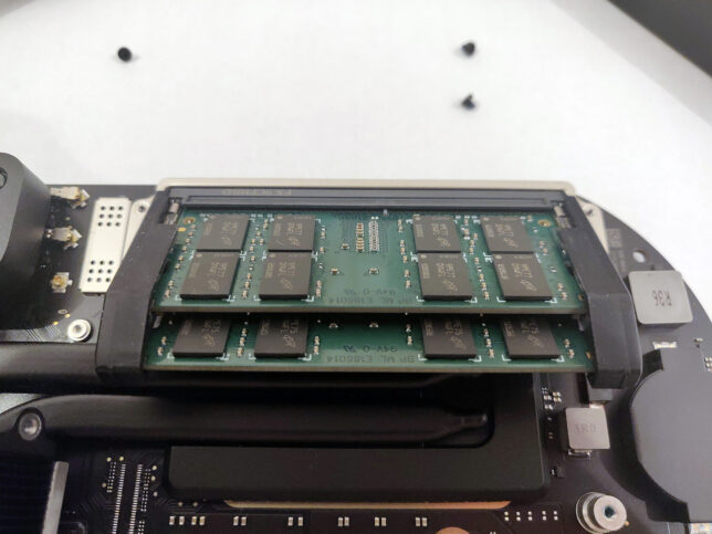
Carefully push the RAM module retainer clips to the side (they have a rubber grommet type covering over them), and the existing SODIMM modules will pop loose.
Remove the old modules and replace with your new ones. Make sure you align the modules in the correct orientation. The slots are keyed, so pay attention to that. Push them down toward the board once aligned and the retainer clips will snap shut and lock them in place.
Replace the RAM ‘cage’ with it’s 4 x hex screws.
Reverse the steps you took above to insert the motherboard tray back into the chassis and re-attach all the cables and connectors in the correct order.
Make sure you didn’t miss any screws or cables when reconnecting everything.
OpenFaaS is an open source project that provides a scalable platform to easily deploy event-driven functions and microservices.
It has great support to run on ARM hardware, which makes it an excellent fit for the Raspberry Pi. It’s worth mentioning that it is of course designed to run across a multitude of different platforms other than the Pi.
Getting Started
You’ll work with a couple of different CLI tools that I chose for the speed at which they can get you up and running:
arkade – a golang based CLI tool for quick and easy one liner installs for various apps / software for Kubernetes
There are other options like Helm or standard YAML files for Kubernetes that you could also use. Find more information about these here.
I have a general purpose admin and routing dedicated Pi in my Raspberry Pi stack that I use for doing admin tasks in my cluster. This made for a great bastion host that I could use to run the following commands:
Install arkade
# Important! Before running these scripts, always inspect the remote content first, especially as they're piped into sh with 'sudo'

# MacOS or Linux
curl -SLsf https://dl.get-arkade.dev/ | sudo sh

# Windows using Bash (e.g. WSL or Git Bash)
curl -SLsf https://dl.get-arkade.dev/ | sh
Install faas-cli
# Important! Before running these scripts, always inspect the remote content first, especially as they're piped into sh with 'sudo'

# MacOS
brew install faas-cli

# Using curl
curl -sL https://cli.openfaas.com | sudo sh
Deploying OpenFaaS
Using arkade, deploy OpenFaaS with:
arkade install openfaas
If you followed my previous articles in this series to set your cluster up, then you’ll have a LoadBalancer service type available via MetalLB. However, in my case (with the above command), I did not deploy a LoadBalancer service, as I already use a single Ingress Controller for external traffic coming into my cluster.
The assumption is that you have an Ingress Controller setup for the remainder of the steps. However, you can get by without one, accessing OpenFaaS by the external gateway NodePortservice instead.
The arkade install will output a command to get your password. By default OpenFaaS comes with Basic Authentication. You’ll fetch the admin password you can use to access the system with Basic Auth next.
Grab the generated admin password and login with faas-cli:
OpenFaaS will have deployed with two Gateway services in the openfaas namespace.
gateway (ClusterIP)
gateway-external (NodePort)
Instead of relying on the NodePort service, I chose to create an Ingress Rule to send traffic from my cluster’s Ingress Controller to OpenFaaS’ ClusterIP service (gateway).
You’ll want SSL so setup a K8s secret to hold your certificate details for the hostname you choose for your Ingress Rule. Here is a template you can use for your OpenFaaS ingress:
You should now be able to access the OpenFaaS UI with something like https://openfaas.foo.bar/ui/
Creating your own Functions
Life is far more fun on the CLI, so get started with some basics with first:
faas-cli store list --platform armhf – show some basic functions available for armhf (Pi)
faas-cli store deploy figlet --platform armhf – deploy the figlet function that converts text to ASCII representations of that text
echo "hai" | faas-cli invoke figlet – pipe the text ‘hai’ into the faas-cli invoke command to invoke the figlet function and get it to generate the equivalent in ASCII text.
Now, create your own function using one of the many templates available. You’ll be using the incubator template for python3 HTTP. This includes a newer function watchdog (more about that below), which gives more control over the HTTP / event lifecycle in your functions.
Grab the python3 HTTP template for armhf and create a new function with it:
# Grab incubator templates for Python, including Python HTTP. Will figure out it needs the armhf ones based on your architecture!
faas template pull https://github.com/openfaas-incubator/python-flask-template
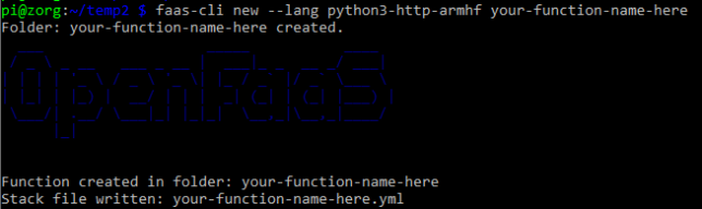
faas-cli new --lang python3-http-armhf your-function-name-here
Success – a new, python3 HTTP function ready to go
A basic file structure gets scaffolded out. It contains a YAML file with configuration about your function. E.g.
The YAML informs building and deploying of your function.
A folder with your function handler code is also created alongside the YAML. For python it contains handler.py and requirements.txt (for python library requirements)
def handle(event, context):
    # TODO implement
    return {
        "statusCode": 200,
        "body": "Hello from OpenFaaS!"
    }
As you used the newer function templates with the latest OF Watchdog, you get full access to the event and context in your handler without any extra work. Nice!
Build and Deploy your Custom Function
Run the faas up command to build and publish your function. This will do a docker build / tag / push to a registry of your choice and then deploy the function to OpenFaaS. Update your your-function-name-here.yml file to specify your desired docker registry/repo/tag, and OpenFaas gateway address first though.
faas up -f your-function-name-here.yml
Now you’re good to go. Execute your function by doing a GET request to the function URL, using faas invoke, or by using the OpenFaaS UI!
Creating your own OpenFaaS Docker images
You can convert most Docker images to run on OpenFaaS by adding the function watchdog to your image. This is a very small HTTP server written in Golang.
It becomes the entrypoint which forwards HTTP requests to your target process via STDIN or HTTP. The response goes back to the requester by STDOUT or HTTP.
Hopefully this gave you a good base to get started with OpenFaaS. We covered everything from deployment and configuration, to creating your own custom functions and images. Have fun experimenting!
I recently came across a scenario requiring CloudWatch log ingestion to a private Splunk HEC (HTTP Event Collector).
The first and preferred method of ingesting CloudWatch Logs into Splunk is by using AWS Firehose. The problem here though is that Firehose only seems to support an endpoint that is open to the public.
This is a problem if you have a Splunk HEC that is only available inside of a VPC and there is no option to proxy public connections back to it.
The next thing I looked at was the Splunk AWS Lambda function template to ingest CloudWatch logs from Log Group events. I had a quick look and it seems pretty out of date, with synchronous functions and libraries in use.
So, I decided to put together a small AWS Lambda Serverless project to improve on what is currently out there.
async / await, and for promised that wrap the synchronous libraries like zlib.
A module that handles identification of Log Group names based on a custom regex pattern. If events come from log groups that don’t match the naming convention, then they get rejected. The idea is that you can write another small function that auto-subscribes Log Groups.
Secrets Manager integration for loading the Splunk HEC token from Secrets Manager. (Or fall back to a simple environment variable if you like).
Serverless framework wrapper. Pass in your Security Group ID, Subnet IDs and tags, and let serverless CLI deploy the function for you.
Lambda VPC support by default. You should deploy this Lambda function in a VPC. You could change that, but my idea here is that most enterprises would be running their own internal Splunk inside of their corporate / VPC network. Change it by removing the VPC section in serverless.yml if you do happen to have a public facing Splunk.
You deploy it using Serverless framework, passing in your VPC details and a few other options for customisation.
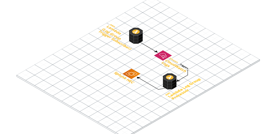
Once configured, it’ll pick up any log events coming in from Log Groups you’ve ‘subscribed’ it to (Lambda CloudWatch Logs Triggers).
These events get enriched with extra metadata defined in the function. The metadata is derived by default from the naming convention used in the CloudWatch Log Groups. Take a close look at the included Regex pattern to ensure you name your Log Groups appropriately. Finally, they’re sent to your Splunk HEC for ingestion.
For an automated Log Group ingestion story, write another small helper function that:
Looks for Log Groups that are not yet subscribed as CloudWatch Logs Triggers.
Adds them to your CloudWatch to Splunk HEC function as a trigger and enables it.
In the future I might add this ‘automatic trigger adding function’ to the Github repository, so stay tuned!
You’ve got a SNS topic in Account A and you wish to subscribe a Lambda function to this topic in Account B.
Setting this up requires configuration on both account sides with resource-based permission policies being applied to SNS in one account and Lambda in the other.
In other words, you’ll need to setup the permissions for SNS and Lambda to allow both subscription and invocation.
Getting Started
You should already have your SNS topic in Account A and a suitable Lambda function subscriber in Account B. For example:
Account A Id: 5556667778 (SNS topic lives here)
Account B Id: 12345678901 (Lambda function lives here)
Configure SNS topic in Account A to allow Subscriptions from Account B
Use the AWS CLI to add a resource-based permission policy to the SNS topic (using it’s ARN). This will allow the Receive and Subscribe actions from Account B.
Configure the Lambda function in Account B to allow invocation from the SNS topic in Account A
Next, add a resource-based permission policy to your Lambda function in Account B. This policy will effectively allow the specific SNS topic in Account A to invoke the Lambda function.
It’s always good practice to follow the principle of least privilege (POLP). In this case you’re only allowing the specific SNS topic in one account to invoke the specific Lambda function you’re adding the policy to.
Subscribe the Lambda function in Account B to the SNS topic in Account A
Of course you’ll need to actually subscribe the Lambda function to the SNS topic. From Account B (where your Lambda function is setup), run the following command to subscribe it to the SNS topic in Account A.